A Homebrew CNC Milling Machine
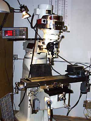
In January of 1999 I completed the conversion of a standard knee mill to CNC operation. The original mill was an Acer Ultima 3VS with 3-axis digital readout and a Servo power feed. The picture shows the mill as delivered to my shop. An interesting anecdote ... I bought this mill from Theodore Maiman, who in 1960 built the first LASER.
As a long-time Macintosh user, I wanted to use a Mac to control the mill. This meant writing my own software. Actually, I had done most of this work several years ago for my first CNC tool -- a router table. It took just a few days to update the old software to run the new mill.
I was able to purchase some surplus hardware, and get good advice, from Bill Griffin in the Los Angeles area. Bill is a consultant in CNC conversions and retrofits machines for hire.
I bought three large stepper motors. These were 56 frame motors with 1400 oz/in of torque. For drivers I acquired three Compumotor OEM 650 microstepping drivers. I built a small microcontroller to interface between the Macintosh serial port and the Compumotor drivers. It's barely more than a serial to parallel converter, but it also understands the pulse width requirements of the Compumotor drivers and will manage limit switches when they're added.
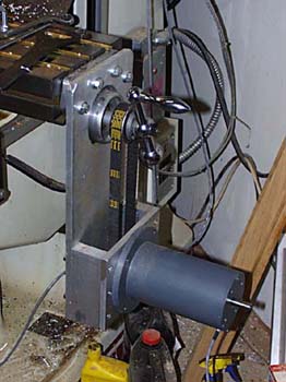
The power feed was to become superfluous, so I removed it and mounted one of the stepper motors in its place. The picture shows the X axis of the mill with the motor mounted to the right end of the mill table. The mounts are basically plates of 1/2" aluminum with a sliding fit to tension a 3/4" timing belt. I placed the top toothed pulley on the mill's crank shaft in place of the indicator dial. This allows me to crank the machine by hand when the motors are unpowered. The top plate is bolted to the existing bearing housing, so no new holes needed to be drilled in the mill itself.
The mounting of the Y axis is similar. Two sliding plates tension a 3/4" timing belt, with the top pulley mounted on the crank shaft. As before, no new holes were drilled into the machine. This arrangement of the motor keeps it out of the way of the operator.
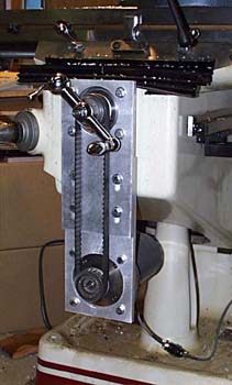
The Z axis was more challenging. I still didn't want to drill new holes in the mill. Though many people motorize the knee, it seemed unnecessary to move all that metal just to raise and lower the cutter. So I fabricated a fixture to slip on the quill in place of the normal hand lever. This fixture engages the quill feed and carries a toothed pulley for a timing belt to the motor. There is a 2:1 ratio to the motor, giving the quill feed better resolution and more power. Though it's been removed in this picture, a hand lever screws into the aluminum fixture just beside the pulley, so the quill can be operated by hand when the motor is unpowered.
My control software is original, written in C, and runs on a Macintosh computer. It provides manual control of the motors (jog) and will run program files written in my own language or in a limited set of g-code. I draw parts in Adobe Illustrator and my software translates the PostScript files into my native machine language or g-code to run the mill. It can also run g-code files from CAD programs as long as they conform to the set of g-code I've implemented.
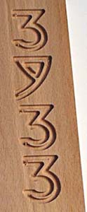
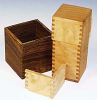
I've also added a couple of woodworking functions to my program. One of them cuts perfect box joints and the other cuts "dentil" molding for clock cases (see pictures below).
Early products of the CNC mill
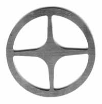
More wood work than metal work. Here's a spoked brass gear blank, box joints, house numbers.
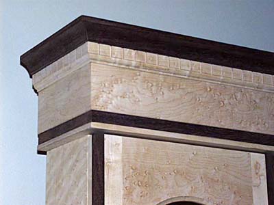
Dentil molding on clock case
02-16-99
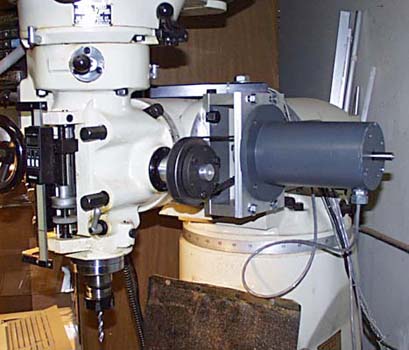
Cutting clock gears
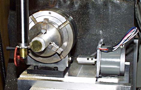 I've now finished interfacing a Sherline rotary table to the milling machine for the purpose of cutting clock gears. A Thornton gear cutter is held in a vertical steel bar mounted in the collet of the milling machine. The rotary table is mounted vertically and held in the mill vise. A small stepper motor rotates the table under computer control. I've now finished interfacing a Sherline rotary table to the milling machine for the purpose of cutting clock gears. A Thornton gear cutter is held in a vertical steel bar mounted in the collet of the milling machine. The rotary table is mounted vertically and held in the mill vise. A small stepper motor rotates the table under computer control.
I've added a special "gear cutting" function in the computer program. It allows you to enter the number of teeth desired and the distance for the cutter to travel front to back (the Y axis) to cut the tooth. You can click on "Next" or "Previous" buttons to advance the table one tooth position, "Cut" to cut one tooth at the current position, or "Cut gear" to cut the whole gear. During operation the number of the tooth being cut is shown on the screen.
The system will cut gears with any number of teeth without any indexing plates. The resolution of positioning is 1/80th of a degree and, when tooth counts do not divide evenly into 360 degrees, each position is calculated within this tolerance. The 39 tooth wheel seen in the picture is .868" in diameter and takes 5 minutes to cut, though it requires no attention during this time.
Since this page was prepared, I've collaborated with Sherline Products to produce a self-contained CNC Rotary Indexer as an accessory for milling machines. This tool has it's own controller for programmed motion of a 4" rotary table. It can also be driven with STEP and DIRECTION or SENSE and ACKNOWLEDGE signals from an existing controller for a 4th axis. A modified program for this controller allows it to be used with other rotary tables that have gear ratios of 40:1 or 90:1. Click here for a description of this tool.
Bryan Mumford
Santa Barbara, California
December 19, 1999
|